Understanding PID Control for Balancing a Two-Wheeled Robot
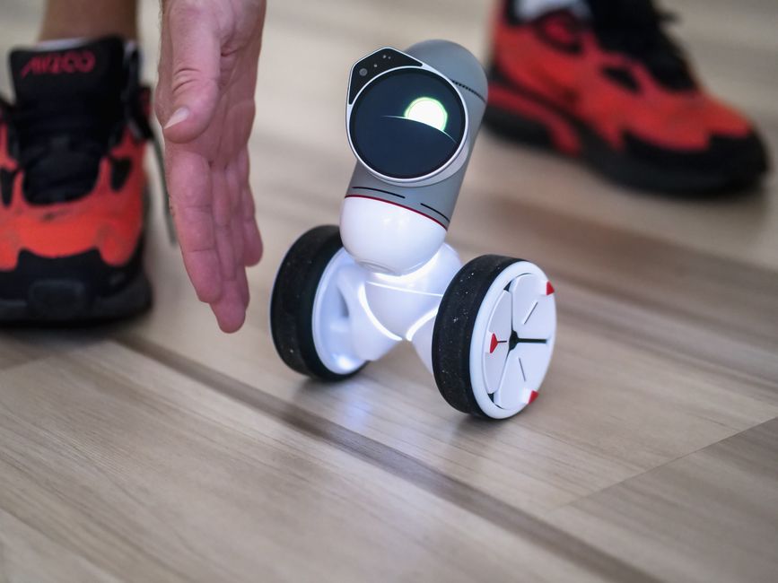
Balancing a two-wheeled robot is a classic control problem that demonstrates the principles of feedback systems in a tangible way. The challenge lies in maintaining an upright position against disturbances such as uneven surfaces, motor nonlinearities, and sensor noise. Proportional-Integral-Derivative (PID) control is a widely used method to address this challenge because of its simplicity and effectiveness when tuned appropriately. This article explores how PID control works in the context of a self-balancing robot and discusses a structured approach to adjusting the gains, supported by real-time response plots from the RoboCore test platform.
The core idea behind a balancing robot is to measure the tilt angle using an inertial measurement unit (IMU) and then adjust the motor speeds to keep the robot upright. The PID controller computes an error signal — the difference between the desired angle (usually zero, representing vertical) and the measured angle — and applies a correction based on three terms: proportional, integral, and derivative. Each term plays a distinct role in the robot’s behavior, and understanding these roles is essential for systematic tuning. The following sections break down the control process, the tuning methodology, and the practical observations that can guide engineers and hobbyists alike.
Rather than relying on trial-and-error, a methodical tuning process can save time and improve performance. The RoboCore test platform provides real-time plots of angle, angular velocity, and motor commands, allowing users to see how each gain adjustment affects the system. By walking through the steps in a logical order, it becomes possible to reach a stable balance without overshoot or excessive oscillation.
Role of the PID Controller in Keeping the Robot Upright
A two-wheeled robot is an inverted pendulum system, inherently unstable without active control. The PID controller works continuously to correct deviations from the upright position. The proportional term applies a corrective torque proportional to the current tilt angle: a larger tilt results in a stronger motor command to bring the robot back. However, proportional control alone often leads to steady-state error or oscillation because the robot may overshoot and then correct too late. The derivative term anticipates future errors by reacting to the rate of change of the angle, adding damping to reduce overshoot. The integral term accumulates past errors over time, helping to eliminate small offsets caused by motor friction or slight imbalances in sensor calibration.
Together, these three terms form a control signal that drives the motors. In practice, the controller output is calculated as the sum of the P, I, and D terms, each multiplied by their respective gains (Kp, Ki, Kd). The challenge is to find gain values that yield a fast response without instability. The RoboCore platform allows logging of the angle over time, so when a disturbance is applied, the response plot clearly shows overshoot, settling time, and steady-state error. By examining these plots, the effect of each gain can be correlated with the observed behavior.
Understanding the Three Terms: Proportional, Integral, and Derivative
Before tuning, it helps to examine how each term influences the robot’s motion independently. The proportional gain Kp determines how aggressively the robot reacts to the current angle error. A high Kp makes the system respond quickly but can introduce overshoot and oscillation if the derivative damping is insufficient. A low Kp leads to a sluggish response, and the robot may tip over before the motors can react. The derivative gain Kd provides damping by opposing rapid changes in angle. In a balancing robot, increasing Kd can reduce overshoot and make the system more stable, but too much derivative gain can amplify sensor noise, causing motor jitter.
The integral gain Ki addresses persistent offsets. For example, if the robot’s center of mass is slightly off-center, the proportional and derivative terms may never bring the angle exactly to zero because they rely on immediate error or its change. The integral term accumulates the error over time and adds a correction that eventually eliminates the offset. However, if Ki is too large, the integral term can wind up, causing slow oscillations or overshoot when the error changes sign. In the context of a self-balancing robot, integral action is often used sparingly because the system is already prone to drift, and excessive Ki can lead to instability.
On the RoboCore test platform, the effect of each term can be visualized by plotting the angle over time after applying a small push. A pure P controller might show a constant offset or sustained oscillations. Adding D smooths the response, while adding I reduces the final angle error to zero. These plots serve as a diagnostic tool that makes the tuning process more transparent.
Step-by-Step Gain Adjustment Procedure
A common approach to tuning a PID controller for a balancing robot follows a sequential order: first set all gains to zero, then adjust Kp until the robot oscillates evenly, then add Kd to dampen the oscillations, and finally add Ki to correct any remaining offset. The following steps outline a practical method using the RoboCore platform’s real-time plotting:
- Initialization: Ensure the robot is mounted on a stand or held securely so it can pivot freely without falling. Set Kp, Ki, and Kd to zero. This may cause the robot to fall immediately, so a safety tether or hand support is recommended.
- Adjust Kp: Gradually increase Kp in small increments (e.g., 0.1) while observing the angle plot. Look for the point where the robot begins to oscillate around the upright position with a consistent amplitude. This is the critical gain. Make a note of the oscillation frequency.
- Add Kd: With Kp at the critical value, begin increasing Kd until the oscillation is dampened. The goal is to achieve a critically damped response where the robot returns to upright without overshoot. Increase Kd carefully because too much can cause motor chatter due to noise. The plot should show a smooth convergence to zero angle.
- Refine Kp and Kd together: After adding Kd, it is often possible to increase Kp further for faster response while maintaining stability. Adjust both in small steps, observing the plot for overshoot and settling time.
- Introduce Ki: If the robot settles at a small non-zero angle (steady-state error), add a small Ki value (e.g., 0.01). Increase slowly until the error disappears. Be cautious of integral windup; the plot will show a slow drift if Ki is too high.
- Final fine-tuning: Apply gentle pushes to the robot and observe the response. Adjust gains slightly to balance speed and stability. Save the final gain values for reuse.
Throughout this process, the real-time angle plot from the RoboCore platform provides immediate feedback. Each gain change alters the shape of the response curve, making it possible to iterate quickly without relying on guesswork.
Interpreting Real-Time Response Plots
Response plots from the test platform typically show the measured angle on the y-axis against time on the x-axis. A well-tuned system will exhibit a rapid rise to the target angle (zero) with minimal overshoot and a short settling time. Overshoot appears as a spike beyond zero before returning, while steady-state error shows as a flat line offset from zero. When Kp is too high, the plot shows sustained oscillations of constant amplitude. When Kd is too low, the oscillations decay slowly. When Ki is too high, the plot may show a slow sinusoidal drift or a prolonged undershoot.
In addition to the angle plot, the platform can display motor command values. Large spikes in command indicate that the controller is demanding high torque, which may exceed motor limits or cause power supply issues. Balancing the gains to keep commands within a reasonable range while maintaining stability is an important practical consideration. The plots also reveal nonlinearities such as stiction or dead zones, which can inform adjustments to the control loop or suggest mechanical improvements.
The RoboCore test platform enables users to record and compare multiple tuning runs, making it easier to see the effect of a single gain change without relying on memory or subjective observation.
Practical Considerations and Limitations
While PID control is effective, it is not a universal solution. The robot’s physical properties — such as wheel diameter, motor torque, battery voltage, and surface friction — all influence the optimal gains. A set of gains that works on a smooth floor may cause instability on carpet or on inclines. Additionally, sensor noise and sampling rate affect the derivative term’s performance. Low-pass filtering on the IMU data can reduce noise but introduces phase lag, which may destabilize the loop. The tuning procedure described above assumes a clean sensor signal and a consistent environment; in real applications, robustness across varying conditions may require gain scheduling or adaptive control.
Another limitation is the integral term’s tendency to cause windup when the robot is held at a large angle for a prolonged period, such as when starting from a tipped position. Anti-windup mechanisms — like clamping the integral sum or using conditional integration — are often implemented to prevent this. The RoboCore test platform includes options to enable such features, and the response plots can help verify that windup is not occurring.
Finally, it is worth noting that PID tuning is a skill that improves with practice. The step-by-step procedure provides a reliable starting point, but each robot has its own characteristics. Patience and careful observation of the response plots are key to achieving stable balance. Engineers and hobbyists are encouraged to experiment within safe boundaries and document their findings for future reference.